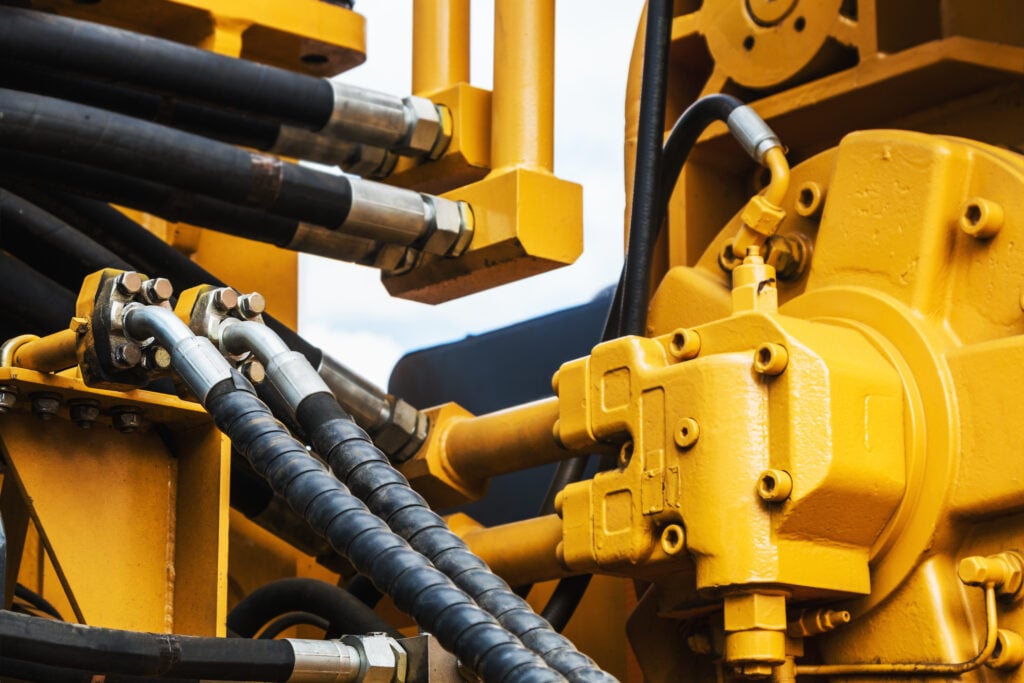
Hydraulic connections mate pipes, hoses or tubes together or to components such as cylinders, pumps, valves or ports in other equipment. They are used in to complete a leak free hydraulic fluid system. These components combine to ensure the system is free of leaks or other failure under high pressures. Because of certain connection configurations and applications, flange fittings or separate flanges are the best or sometimes only practical solution to make an efficient and leak free connection.
Flange connections are typically used in applications that will encounter exceptionally high pressures when using pipe or tubing with an OD over 7/8 inches. They may be
bolted together to mate two sections of pipe (tube or hose), or bolted or screwed into the component to secure a flange fitting or section of pipe. Flanges can also be disassembled for easy access to modify the system, clean or inspect it. Certain flanges may also be permanently welded together or to the port section of the component (motor housing, valve port, etc.). More commonly, a flanged joint is made by bolting two flanges together with a gasket in-between to ensure a secure seal.
There are two primary types of flanges:
- SAE Code 61 flanges are used for applications requiring working pressure of 3,000 to 5,000 PSI
- SAE Code 62 flanges are used for applications requiring working pressure of up to 6,000 PSI
The hydraulic flange standard is ISO 6162, which includes SAE Code 61 and 62 or SAE J518 UNC thread North American Standard, along with International standards with metric threads.
NOT Interchangeable
It is important to note that the two flange style codes (61 and 62) are not interchangeable due to their pressure ranges and their different bolt patterns.
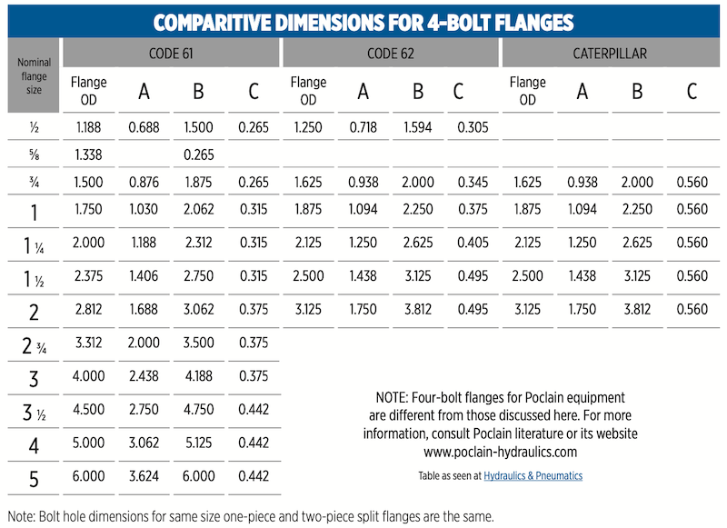
As shown in this diagram of overlapping code 61 and code 62 4-bolt flanges the dimensional placement of holes are close, but not identical. Note the difference in the bolt-hole’s center-to
-center dimensions.
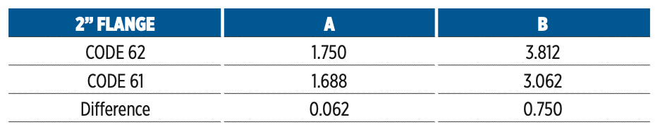
As shown in the flange diagram and chart below, the distance
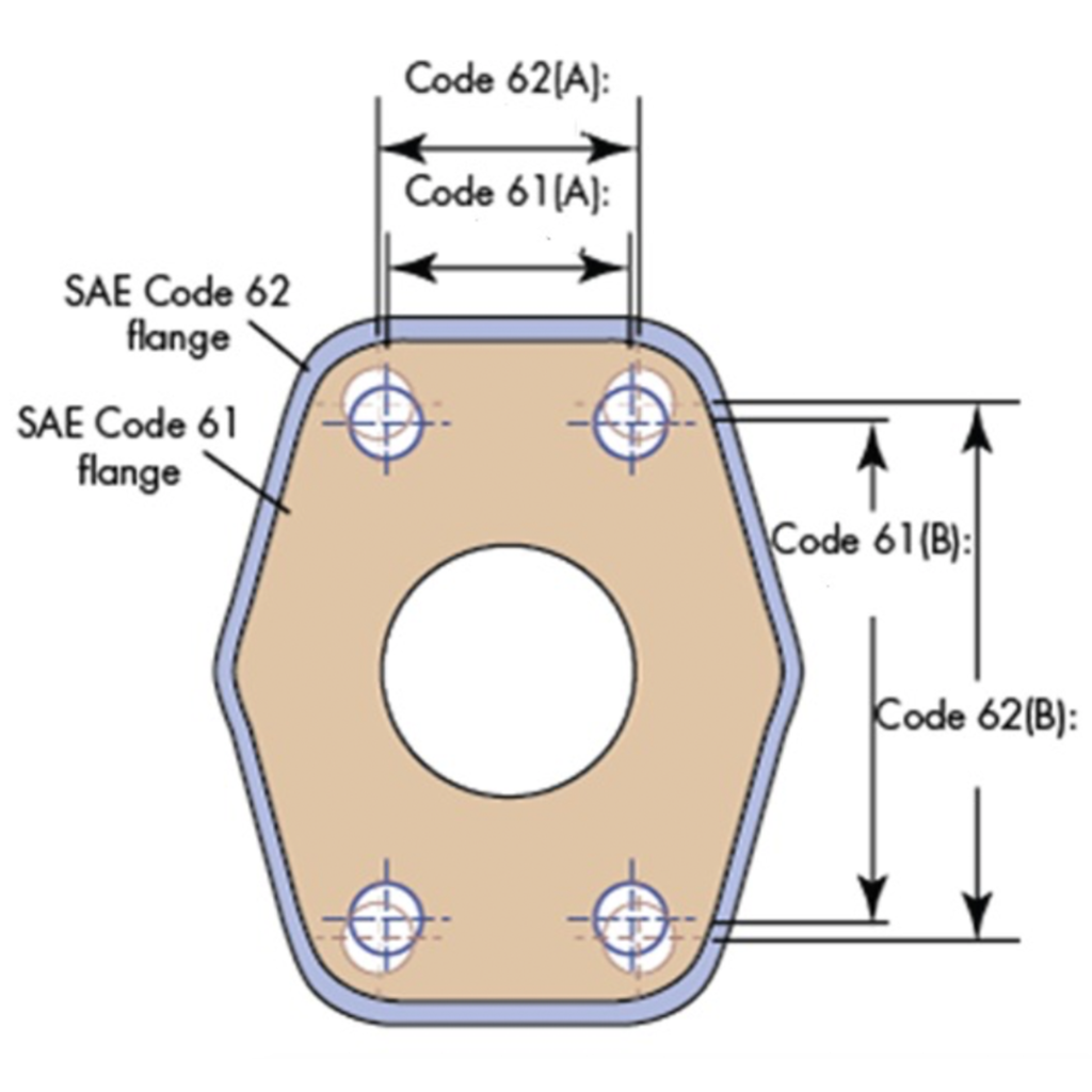
between hole centers for dimension A in a 2 inch Code 61 versus a Code 62 flange varies by as little as 0.062 inches and for dimension B is offset by a significant 0.75 inches.
There is also another style that must be accounted for and not interchanged with Code 61 or 62 flanges. This other 4 bolt flange often found in the field is made for Caterpillar equipment and called (not surprisingly) a Caterpillar flange. This style is almost an exact match to the SAE Code 62 4-bolt flange with one major difference:
The flange head on an SAE Code 62 has a thickness which ranges from 0.305 inches on the 1⁄2 inch flange to 0.495 inches on the 2 inch flange, where the Caterpillar flange head thickness is 0.560 inches for all 4-bolt flanges. Hence an important distinction as to why they should not be interchanged.
Although many SAE 4-bolt hydraulic flanges might look alike or that different flanges and fittings might appear to be compatible, that is usually not the case. SAE Code 61, SAE Code 62 and Caterpillar 4-bolt flanges have dimensional variations and slight differences in configuration, plus the differences in allowable working pressure, do not allow them to be used together or interchanged. Take the example from on the The Fluid Power Safety InstituteTM website:
A diesel mechanic was installing a new hydraulic motor onto a machine. While reconnecting the hydraulic hose he inadvertently used a 4-bolt split flange that did not line up with the holes on the motor housing. Suspecting the holes in the motor were not tapped in the proper place he filed the holes in an attempt to have them line up with the flange. He essentially modified a 6,000 PSI SAE Code 62 4-bolt flange to mate with a 3,000 PSI SAE Code 61 motor.
This was an unfortunate mistake and one that could have been catastrophic to the system if it had been the other way around; modifying a 3,000 PSI bolt flange with a 6,000 PSI motor. An obvious system failure would have occurred, or worse a system failure that blew the assembly off causing severe damage or physical harm. This is a prime example of the importance of using only matched and properly rated components. This example illustrates the importance of properly matching flanges with each other or to
the intended component. To recommend guidelines for avoiding the mismatching of 4-bolt flanges, the Fluid Power Safety Institute (FPSI) developed the table below for common types and sizes.
Benefits of Flanges
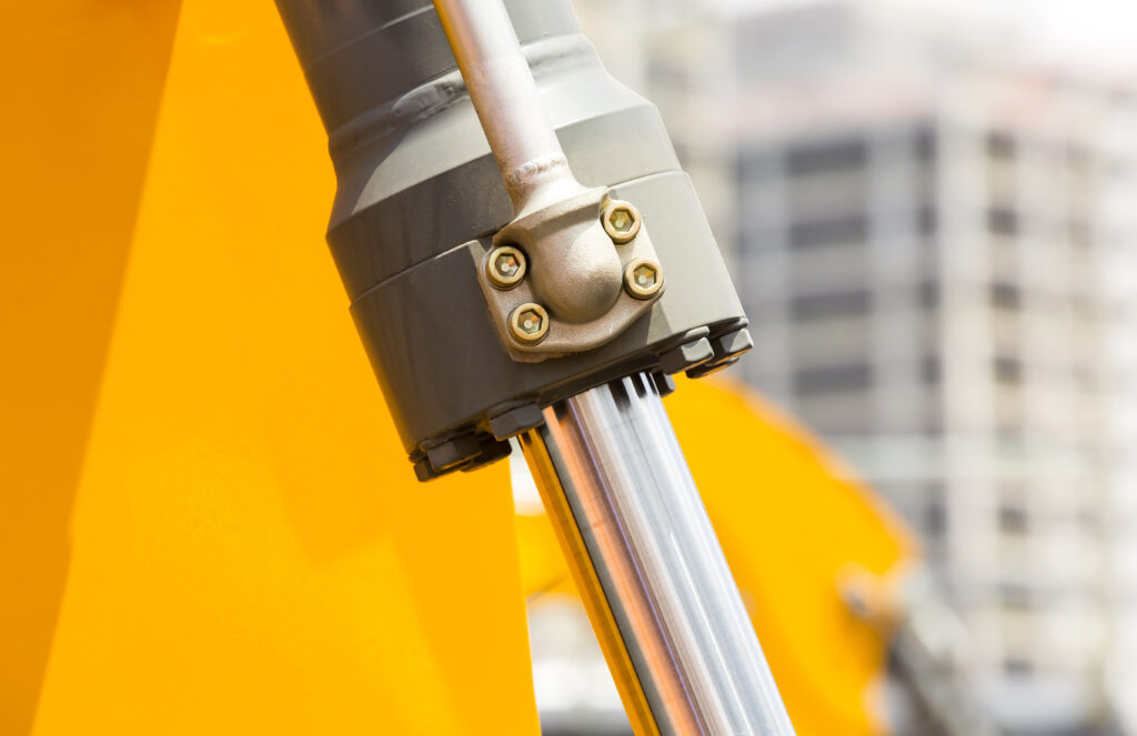
Though there are specific applications where flanges and/or flange fittings are the only practical choice (particularly in larger, high pressure piping applications), flanges sometimes provide benefits to the piping system that traditional hydraulic fittings do not. For example, in those larger OD applications flanges are often able to be connected to pipe (tube or hose) and component ports more easily than threaded fittings or adapters. In many severe service applications on mobile construction equipment flanged connections are best for:
- Ease of assembly in tight spaces where wrenches might not have clearance if installing traditional fittings and they are more easily assembled with moderate torque.
- Hard to reach areas where flexibility is required, eliminating the need for adapters in the tube, pipe
or hose line. - Large hose, tube or pipe connections where shock, vibration, high pressure and/or pressure surges are present, which could more easily damage a traditional large hydraulic fitting.
- Making connections that allow for easy maintenance in rigid lines such as continuous pipes or metal tubes.
- Reducing the chance of components becoming loose in rigorous hydraulic applications.
FLANGE FITTINGS & HOW THEY FIT IN
The fluid power industry is working to make a shift to using connections with an elastomeric, O-ring type seals to minimize leakage. Among other styles, these fittings include the SAE straight thread, face seal, ISO 6149, SAE J518 (Code 61 and Code 62) flange fittings and flanges (Code 61 and Code 62), where the O-ring seal is compatible with the fluid. As covered above, when fitting tube-to-tube (or pipe or hose) a captive
flange is often used. Captive flanges simply slip over the flared tube and are connected to mating flange or other component. Captive flanges are commonly used with MJ-Flange Straight fittings (aka flange adapters), where there is smooth clearance to slide over the fitting allowing the flange head on the fitting to seat into it. Yet split flanges are used when 45° or 90° flange fittings are used (i.e. MJ- Flange 45 or 90). Split flanges come in kits (either for Code 61 or 62) which include:
- Two halves of the flange that fit around the fitting where the fitting’s flange head meets
- The accompanying O-ring seal
- Four bolts and washers to secure the flange and fitting to its intended port
Flange fitting connections are easy to assemble and provide the best option in larger diameter applications, especially when under high pressure. They provide significant advantages versus threaded fittings in these larger, more severe applications, such as:
- Easier to assemble in tight spaces
- Easy to disassemble for maintenance of reconfiguring of the system
- Large connections of over 7/8 inch up to 5 inch O.D tube or pipe – for Code 61 only
- Less torque required for tightening the four bolts versus achieving proper torque for a comparable large size fitting
- Provides up to 6,000 PSI capability through 2″ size – for Code 62 only, 5,000 PSI for Code 61
- Single point of sealing between tube, pipe, hose and/or component port connection
SAE J518 MAXIMUM WORKING PRESSURE RATINGS
FOR CODE 61 AND CODE 62 FLANGE FITTINGS
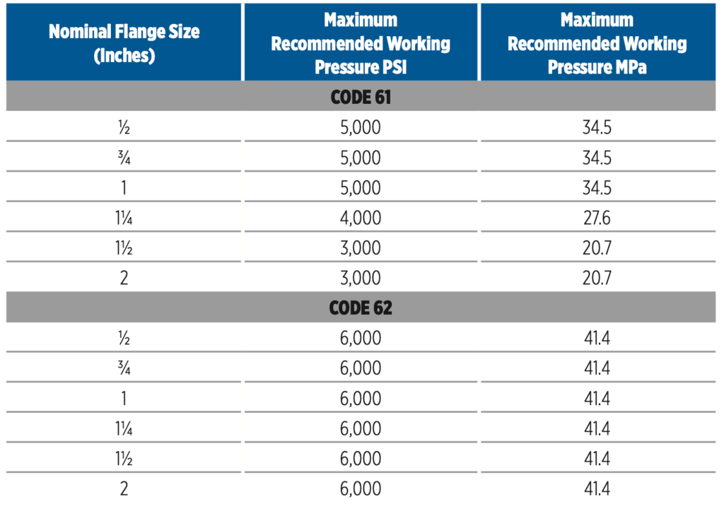
MPa (Mega Paskels) — 1 MPa = 145 PSI
Among the category of flange fittings (or flange adapters) are flanges plugs, which are used to cap off or block the flow in the pipe. Flange plugs are basically a flange without a center hole which closes the end of a pipe when bolted to a standard mating flange. Depending on the system requirements these plugs are typically gas or liquid tight. For gray water subsurface irrigation they are sometimes used to force waste through perforated holes in the pipe, driven by system pressure.
Conclusion
Though many SAE 4-bolt hydraulic flanges look quite similar to each other, SAE Code 61, SAE Code 62, and Caterpillar 4-bolt flanges exhibit small dimensional and physical differences that cannot be interchanges. It’s imperative to make sure the flanges are of the same code and the hole alignments match exactly.
Flange connections use a gasket to ensure a secure seal and are best in conditions of exceptionally high pressures in piping systems of 7/8” OD or larger. They
are used to connect pipe-to-pipe, tube- to-tube, hose-to-hose, etc. Or a single flange is used to bolt a pipe directly onto a component.
Flange fittings (aka flange adapters) are used with split and 4-bolt flanges when the mating connection is a threaded JIC 37° flare or other connection type. High quality flange fittings are made to endure extremely high working pressures and tensile strength, and are designed to perform in a variety of clearance applications. The most popular sizes of flange fittings range from 1/2” to 4”.
When fittings are involved, captive flanges are commonly used with MJ-Flange Straight fittings where there is smooth clearance to slide over the fitting allowing the flange head on the fitting to seat into the flange. Yet split flanges are used with 45° or 90° flange fittings (i.e. MJ-Flange 45 or 90).
A 4-bolt flange connection that complies with SAE J518 and ISO 6162-1 and 6162-2 (Code 61 and Code 62) ensures a leak-free connection and is best in larger sizes under high pressure and for assemblies in tight spaces. These 4-bolt flange port connections allow for the connection of larger sizes and attain high pressures with the capability of assembling at low torques. When compared to equivalent size threaded ports these low torque assemblies are typically the best choice in tight spaces, especially where there is limited wrench clearance.
SOURCES:
Explore the World of Piping
Hydraulics & Pneumatics
Mechanical Contracting Education & Research Foundation
Mobile Hydraulic Tips
The Fluid Power Safety Institute