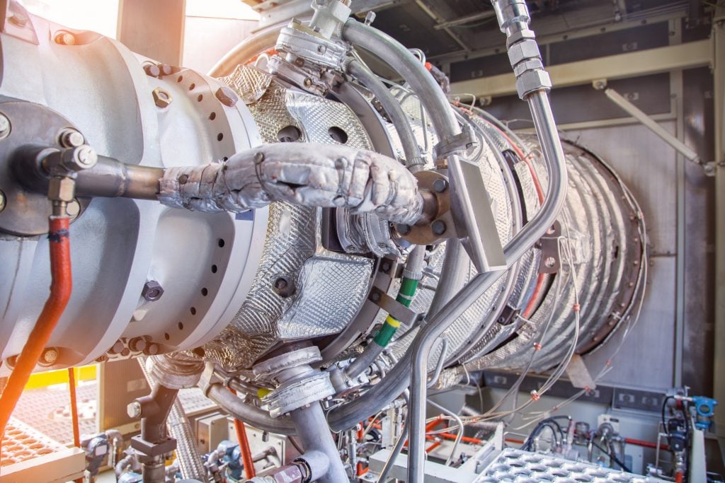
Introduction
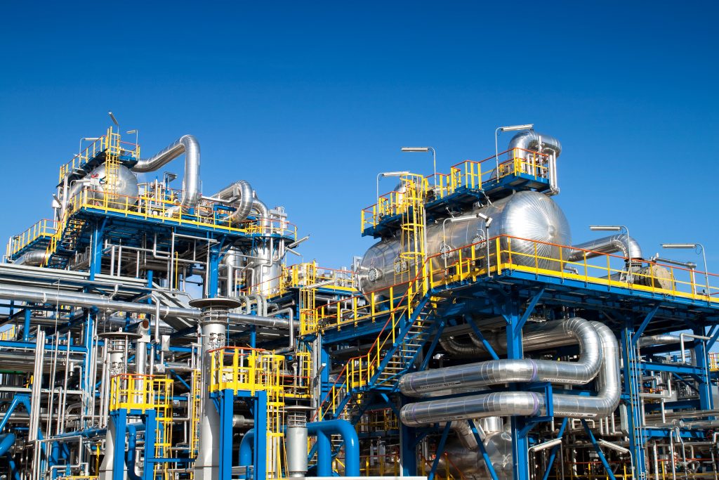
Process measurement and control instrumentation is a vital part of most primary industries, including:
Aerospace
Defense
Power Generation
Chemical Processing
Oil & Gas
Petrochemical
Alternative Fuels
Shipbuilding
Medical Equipment
PM&C instrumentation covers devices and components from control valves, fittings and tubing
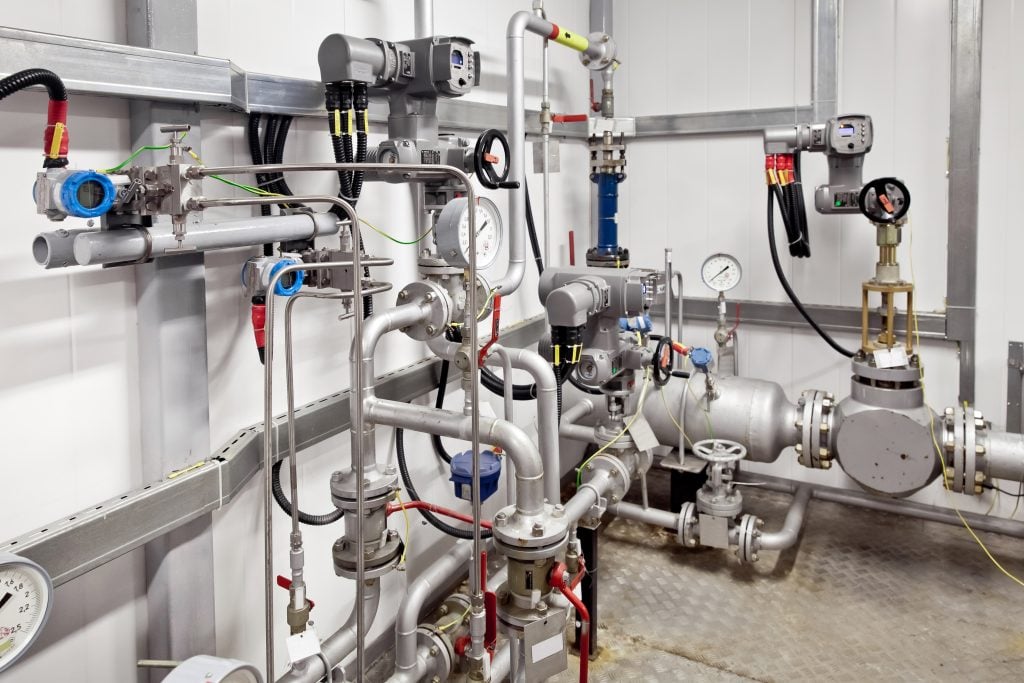
to flow meters, pressure sensors and level gauges.
They are used to transfer, measure and control system
flow, pressure, temperature and provide system calibration.
Instrumentation components are critical to the operations of the plant or a product grouping. Fittings, valves, and tubing are the veins and arteries of the instrumentation system.
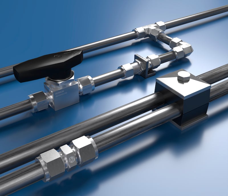
Instrumentation Fittings
TUBE FITTINGS
There are four primary styles of high to low pressure tube fittings. They are differentiated by their end connections and applications, each having its own advantages and disadvantages.
Compression Fittings
Slide over the tube and use a ferrule design to coin and seal on the OD of the tube.
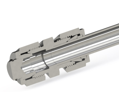
Cone and Thread Fittings (C&T)
Tube ends are coned (chamfered) and threaded. The threads allow for positive lock and sealing of the end face of tube to the fitting body.
Butt Weld Fittings
Permanently joins to the tube end by welding the surrounding metal at the tube end with the fitting.
Push-to-Connect Pneumatic Fittings
Instant connections just by pushing the tube into the fitting.
For most pressure applications (up to 15,000 PSI) fitting sizes are specified by the tubing OD (outside diameter); i.e. 1/4, 3/8, 1/2, 3/4 inch (6, 10, 12, 20 mm). Each style of fitting is available with the specified size end connections and in different configurations, such as:
Straight
Elbow
Tee
Cross
Sometimes they are used as reducing fittings; for instance from a larger size connection such as 3/8 to a smaller, 1/4 tube. Many are also available with the designated style (i.e. compression) on one port to an alternative connection on another port, such as NPT or SAE thread, or male NPT to C&T and many other combinations.
COMPRESSION FITTINGS
The most common and easiest to install are compression fittings. This design uses a sequential grip on the tube. Compression fittings are made up of three components: nut, body and ferrule (single or double). The ferrule coins (compresses) the tube and provides a tight grip on the tube surface. Compression fittings have superior vibration resistance over C&T fittings, but not over butt weld fittings (see below).
This style of fitting does not require any special equipment or tools. Simply slide the tubing into the end connection, and tighten to the required torque with a box wrench (or torque wrench for precision applications). Because of their ease of installation, the use of compression fittings is usually the least expensive overall assembly.
Compression fittings also perform well with thinner walled tubing, which allows for higher flow rates and can be more easily bent and handled. Thinner walled stainless steel tubing used with compression fittings can allow up to 33% more flow through the tubing than the comparable size C&T. Thinner wall seamless tubing can bend with only 70% of the force required to bend a similar heavy wall tube used with C&T fittings. This allows for more flexibility in the application, particularly in field assembly where tube bending equipment is not assessable. However thinner walled tubing may not be able to withstand higher pressures, even in the “medium pressure” range.
CONE AND THREAD FITTINGS
Cone and Thread (C&T) connections are sometimes used in very high pressure applications (up to 150,000 PSI), but are most frequently used for pressures of up to 15,000 PSI. They provide a solid and tight connection, where the tube is chamfered (“coned”) and countersunk into the fitting. To insure a tight seal, the tube ends must be precision formed with a fine surface finish and then threaded so the tubing is assembled firmly against the joint. All of this is typically performed in the field, significantly increasing the installation time and overall cost of using C&T fittings. However, like compression fittings C&T fittings can be broken down and re-assembled for maintenance.
These processes are not always repeatable or consistent. They can also introduce metal shavings and cutting oil into the tubing ID, creating the requirement for an additional cleaning operation. Special training is required to use the tools necessary for installation of C&T fittings. And because the joints are threaded in uncontrolled environments, the fittings can become loose when subject to vibration.
BUTT WELD FITTINGS
Though C&T fittings still provide a very solid connection when installed properly, some studies have found that for every three corrosion failures in the field, there is at least one vibration failure. The assembly that provides the best protection against vibration is a butt weld fitting. Since the metals are being permanently joined together, a well formed butt weld has the best resistance to vibration and fatigue. However, a butt weld fitting connection still has some disadvantages, including cost. The cost of
welding equipment, a specialized welder and the extra labor time can make a butt weld connection the most expensive of the three primary types of instrumentation fitting assemblies.
In addition, field maintenance of fluid systems can be difficult if not impossible with butt weld fittings due to the potential inaccessibility of the joint and/or the maintenance crew not having the tools or skills available to cut and re-weld a connection.
PUSH-TO-CONNECT PNEUMATIC FITTINGS
Push-to-connect fittings use an internal collet and external push button to connect tubing.
These composite fittings are either poly or constructed with nickel plated brass, resin, and polyoxymethylene plastic components. Suitable for polyurethane or nylon tubing, push-to-connect air fittings guarantee leak-free and secure connections for all pneumatic applications. Push-to- connect pneumatic fittings allow instant connections just by pushing the tube into the fitting, without the need for tools, and disconnections are just as easy.
These universally adapted fittings are ideal for both mobile and in-plant applications involving compressed air. They are also offered for metric tubes with BSP threads in taper, parallel
and metric form. Push-to-connect fittings are available in a wide range of body designs and configurations — for tube OD of 1/8” to 1/2”.
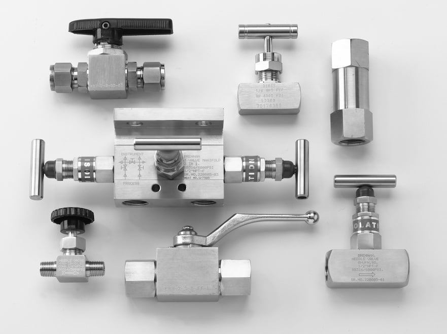
Instrumentation Valves
There are fundamental factors that need to be considered when selecting an instrumentation valve. Some of the most important criteria required for valve selection are listed below. Each application will place higher importance for each of the following factors:
Basic Valve/Packing Designs
Pressure Fluctuation
Pressure & Temperature Considerations
Other key factors include flow media, codes and standards, actuator design options, and flow analysis and
orifice sizing.
It is critical that all aspects of the system be assessed for proper design prior to conducting a valve specification. Understanding the variety of operating conditions will greatly affect the final design selection.
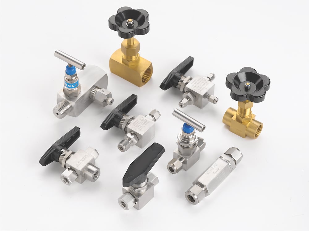
PRIMARY INSTRUMENTATION VALVE DESIGNS
Understanding the variety of ways a valve’s packing has been designed and the types of valve designs that are available play an important role in the specification process. At its basic core, valves consist of a control component such as a ball or a needle, and sometimes incorporate an automatic actuation device for valve operation, as opposed to manual operation. The valve seat controls the flow of the material while the packing limits the leakage between the seat and actuation elements. The overall performance can be dramatically affected by factors such as materials of construction, rigidity, and location on the valve stem and proper valve selection. Among all of the valve designs on the market, generally speaking, the following four valve types will be used in instrumentation applications for flow control, analysis, testing and ensuring maximum safety.
BALL VALVES
A ball valve consists of a ball-shaped component to stop or start fluid flow. In terms of operation, when the valve handle is turned to the open position, the ball rotates to where the hole through the ball moves in line with the valve body inlet and outlet. When the valve is shut, the ball is rotated so that the hole closes the flow opening of the valve body and the flow is stopped. Most ball valve actuators are of the quick-acting type, which only require a quarter turn of the valve handle to open and shut the valve. The most popular instrumentation ball
valves are rated for pressures up to 3,000 PSI and temperatures to 350°F (176°C) with PFA (perfluoro-alkoxy polymer) seats and are available in single (in-line), two-way angle pattern and three-way connections. High quality ball valves have pneumatically tested seats at 1,000 PSI with nitrogen at zero leakage. These ball valves should have hydrostatically tested bodies at 3,000 PSI and seats tested at 2,000 PSI.
Popular ball valve designs are available in 316 stainless steel and brass, and incorporate one-piece packing for clean and accurate samples as well as designs that allow for a drop-in fit for easy replacement of the packing.
DOUBLE BLOCK AND BLEED VALVES
A double block and bleed valve or a DBBV takes the place of 3 separate valves, 2 isolation valves and 1 drain valve. Double block and bleed valves provide isolation from both the upstream and downstream process flow and pressure.
A double isolation and bleed valve stops process fluid from getting to an area that is being worked on. Both in-line valves are closed while the bleeder is open. If fluid were to leak past the first valve the bleeder would drain off before it pressurized the cavity between the upstream and downstream valves. If the bleeder, which may be a needle valve, were to be plugged the downstream valve would keep the process fluid from getting past it.
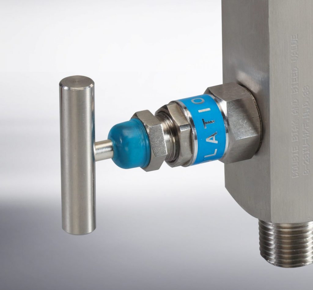
NEEDLE VALVES
A Needle Valve uses a precision engineered tapered pin to gradually open a space for fine control of flow. The flow can be controlled and regulated with the use of the needle. A needle valve has a relatively small orifice with a long, tapered seat, and a needle-shaped plunger on the end of a screw, which precisely fits the seat for
valve shut-off.
When the needle valve screw is turned the plunger retracts allowing flow between the seat and the plunger. However, precise regulation of the flow rate can be controlled when the plunger is completely retracted.
Needle valves are often used in vacuum systems where precise control of gas flow at low pressure is required. They are often used as component parts of other, more complicated valves systems.
Instrumentation needle valves are available with screwed bonnet or integral bonnet. Most are rated for pressures up to 6,000 PSI and temperatures to 4500F (2320C), and are available in straight and angle patterns.
CHECK VALVES
A check valve (aka one-way valve) is a valve that normally allows media (liquid or gas) to flow through it in only
one direction.
Check valves incorporate two-port valves, meaning they have two openings in the body, one for fluid or gas to enter and the other for the media to exit. There are various types of check valves used in a wide variety of applications. Check valves are available in many sizes, yet are typically very small. Most check valves work automatically and do not have a valve handle or stem.
Check valves close from the weight of the check mechanism when back pressure on a spring occurs, allowing the media to flow in only one direction.
Check valves have calibrated cracking pressures, which is the minimum upstream where the valve will operate. Most check valves are rated for pressures of up to 6,000 PSI and temperatures to 3500F (1770C). Depending on the application, cracking pressures are usually set at 1/3, 1, 5 10, 15, 25 and 50 PSI.
MANIFOLD VALVES
Manifolds are used in my many processing applications. They are often used to mount valves or to consolidate the plumbing configuration to interface between valves and ports that are being plumbed into. A manifold is a single block or adjoining blocks, which interface for the valves to mount to or ports for fluid transfer. The ports are then plumbed to the manifold to complete
the circuit.

Because manifold valve systems can be used in modules, other valve types are easily interchangeable and easily mounted to the manifold to customize a system operated by actuators. Valves that are connected in series to manifolds can have a variety of NPT, Metric or ORB ports. This alleviates the need for developing a more complex system of various valve types with different ports, simplifying the system and saving costs.
A manifold can be used without other valves as a fluid cavity with two or more ports combined in series to reduce plumbing. For instance a return line manifold with multiple smaller ports connecting to a larger tank port can eliminate the need for a series of fittings. This lowers cost and reduces potential leak points.
Most manifolds are available in 2, 3 or 5 valve configurations:
· Two valve manifolds are used with instruments such as pressure gauges, pressure transmitters and pressure switches
· Three valve manifolds are the most common. They can incorporate test ports on the process side and drain ports on the instrument side.
· Five valve manifolds are typically used with differential pressure instruments where drain valves are required on the instrument side. They are also common for flushing of they system and the prevention of loss of expensive fluids.
· Three and five valve combination manifolds are used with differential pressure instruments such as differential pressure transmitters, switches and pressure gauges.
PRIMARY DESIGN FEATURES
Most manifold designs have case hardened swiveling stem plugs. This design is ideal for most low, medium and high pressure applications.
· High pressure gas applications typically incorporate a swiveling plug with a soft seat design. The seat materials are reinforced polytetrafluoroethylene (RPTFE), Delrin® and PEEK
· High quality manifolds have a case hardened ball plug in 316 SS. Manifolds made of Hastelloy C, Monel, Inconel® and titanium have tungsten carbide ball plugs.
· Manifold valves should be designed with the “thread above the seal” so that the stem threads are not wetted by the fluid flowing in the system.
· Gland sealing arrangements vary based on temperature ranges. For temperatures up to 180° C, the material used is RPTFE. For temperatures in the 180° C to 270° C range, graphitized seals are used. Beyond 270° C and up to 540° C, grafoil seals are used.
The choice of materials is based on the working fluid and the installation location, where atmospheric conditions may vary and require specific materials to prevent corrosion and withstand vibration.
COMMON MANIFOLD MATERIALS INCLUDE:
• Carbon steel ASTM A105
• Stainless steel ASTM A479, A182, F304, F304L, F316, F316L and F321, available with conformity to NACE MR 01 75 for corrosion resistance.
WHEN EXTREME CORROSION RESISTANCE IS REQUIRED, MATERIALS ARE USUALLY:
• Monel with conformity to NACE MR 01 75 for corrosion resistance
• Inconel, Hastelloy C and titanium
Stainless Steel Tubing
WELDED
Stainless steel welded tubes and pipes are often more cost effective than the equivalent seamless tubing and they can have better surface quality on both the OD and ID because it is made from a strip of roll-formed material and joined with a longitudinal seam made from flat rolled material as opposed to being extruded like seamless tube. In addition, the wall thickness of welded tubing is generally more consistent than that of seamless tube. To ensure this, the internal surface of welded tubes can be checked before manufacturing, which is not possible with seamless. If the concentricity of the wall thickness is difficult to control, as with seamless, it can be challenging to achieve good surface quality.
SEAMLESS
Seamless tubing may come at a higher cost than welded, but the process by which it is formed produces a completely homogeneous tube that allows for working pressures that meets ASME B31.3 Process Piping Code and performs 20% higher than welded tubing. Because of its ability to constantly withstand higher pressures and its superior corrosion resistance, seamless tubing is far more suitable in critical applications than welded tubing.
The allowable working pressures for 304 and 316 stainless steel seamless tubing made to ASTM A269, ASTM/ASME A213 or equivalent provides working temperature of -20°F to 100°F. The tensile strength as specified by ASME B31.3-2002 is 75,000 PSI, with allowable stress of 20,000 PSI.
Seamless stainless steel tubing offers better corrosion resistance and a more homogeneous grain structure. It goes without saying that seamless tubing needs no additional testing for weld integrity and does not present problems with weld-seam orientation and pressure de-rating.
PRIMARY STAINLESS STEEL TUBING SPECIFICATIONS AND RECOMMENDATIONS:
· Annealed 304 or 316 stainless steel tubing to ASTM A 269, A 213 or equivalent
· Tube hardness should not exceed RB 80, where the preferable hardness range is RB 70-78
· Prior to installation, all tubing should be cut square, de-burred and free of any surface defects and imperfections.
· The combination of ASTM F 1387 certified fittings with the recommended ASTM certified seamless tubing and proper techniques is the best way to eliminate hazardous and expensive leaks.
Conclusion
Proper design, selection and installation of any instrumentation system is critical to the energy savings, operation and maintenance of any fluid and gas process operation.
Reducing leaks, maintaining pressure and insuring corrosion resistance makes a system safer, more reliable and extends service life. It is vital that automated processes are optimized to be highly efficient and this is only accomplished with the
correct design and product considerations.
When design pressures are met, fewer cycles are required to meet production schedules, increasing efficiency and maintaining operations costs. The quality of product and accuracy of the initial installation of all components also reduces future maintenance problems and cost overruns.
SOURCES:
Valve Magazine
Fluid Power World, MOBILE HYDRAULICTiPS
Outokumpu
Society of Petroleum Engineers
HandyTube
TECO Technology